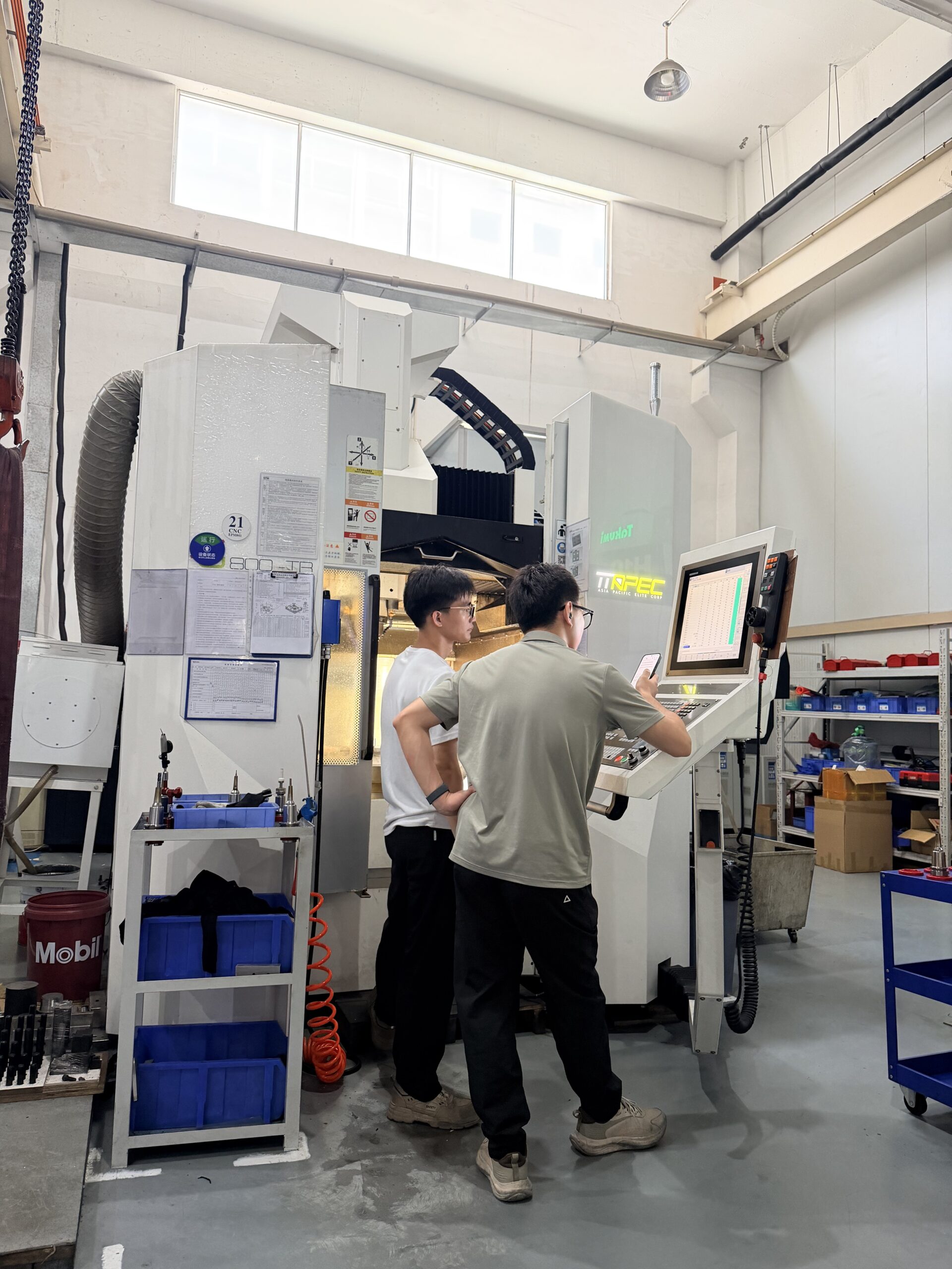
Laser tool setters are non-contact systems that measure cutting tools inside compatible CNC machines. Depending on the device and measurement cycles, they can establish length and diameter values or perform breakage checks without touching the cutting edge. Explore QIDU solutions for repeatable in-machine measurement, process monitoring, and integration into your existing machining workflow
Laser-based checks can reduce manual touch-off work and provide programmed checks before or between machining operations. Because no physical contact is required, this approach can be useful for small or delicate cutters that may deflect under probing force.
Consistent setup routines
Apply defined measurement cycles across repeat jobs and cutter changes
In-machine verification
Check an installed cutter in its actual spindle and holder configuration.
Production monitoring
Add scheduled presence or geometry checks where supported by the equipment and software
Less manual intervention
Reduce operator involvement in recurring checks, subject to the machine’s automation capabilities
How Does Non-Contact Laser Tool Measurement Work
A typical system positions a laser transmitter and optical receiver across an accessible measuring area. During a programmed cycle, the machine moves or rotates the cutting tool through the beam. The receiver detects changes in light as the tool interrupts the beam; the controller or associated electronics uses switching information together with axis positions and calibration data.
Depending on the hardware and software, these signals can support length readings, diameter evaluation, or a presence check. The selected cycle must match the cutter type and objective. This is different from a contact setter, which detects physical deflection or a switching event when the cutter touches a sensing surface.
Optical alignment, clean lenses, proper tool cleaning, machine positioning, and an appropriate measuring routine all influence reliable results.
Where Are Non-Contact Systems Used in Manufacturing
Non-contact checking is particularly relevant where repeated setups or intermediate checks are part of the machining plan. Suitability must be checked against the available space, cutter sizes, and actual operating conditions
Tool-change sequence, accessible travel, and setup workflow
Spindle access, measuring location, and required offsets
Minimum detectable feature, cutter stiffness, and beam positioning
Mixed cutter geometries and repeatable checks between operations
Cycle integration, alarm handling, and check frequency
Which Technical Specifications Matter Most
Compare documented performance under stated test conditions rather than choosing a laser tool setter from a single headline figure.
Selection factor
What to verify before ordering
Repeatability
Test method, conditions, and whether results are stated statistically
Accuracy
Error relative to a reference, distinct from repeatability
Detectable cutter size
Minimum supported tool or feature dimensions for the required cycle
Span and installation
Usable measuring zone, unit dimensions, and mounting clearance
Cutter geometry and speed
Supported cutter profiles, spindle states, and measuring routines
Protection and cleaning
Optical shielding, coolant/chip control, and any required air supply
Integration
Electrical signals, interface modules, CNC macros, and software options
What Is Required for Installation
Compatibility involves more than the controller brand. Before purchase, confirm the complete machine configuration and the intended measuring sequence
Mechanical access: A rigid mounting location, reachable measuring zone, sufficient axis travel, and safe clearance from workholding and moving parts.
Electrical integration: Matching signal interface, wiring, control inputs, and any necessary interface electronics.
Control software: Supported macro functions, measuring cycles, and tool-table handling for the specific configuration.
Site conditions: Coolant and chip exposure, optical protection, tool cleaning, maintenance access, and suitable compressed air where required.
Commissioning: Optical alignment, calibration with a suitable reference, and verification across representative tools and operating conditions.
How Do Laser Systems Support Breakage Detection and Monitoring
Programmed laser checks compare a measured tool condion with a defined reference. What they can detect depends on the sensor,measuring cycle, and configured limits.
WHAT A LASER CHECK CAN TELL YOU
Detect missing or significantly shortened tools
Using a suitable reference and cycle, the machine can check toolpresence or compare measured dimensions against a defined limitbefore the next cut.
Know the limits of basic breakage checks
A successful presence check does not confirm every cutting edge isintact. Small chips, gradual wear, and complex edge damage may require specialized hardware and software.
How Do You Choose the Right System and Supplier
Start with verified specifications and application fit, not a model number or an unqualified accuracy claim. Ask for relevant installation drawings, interface requirements, calibration instructions, available accessories, and confirmation of which measuring cycles are supported.
Also clarify documentation, technical assistance, delivery, and warranty terms for the proposed configuration.
For an accurate quotation, provide:
Machine manufacturer, model, and available installation area
CNC controller model, options, and interface details
Typical cutter types and minimum/maximum diameters
Required measurements, breakage checks, or monitoring functions
Coolant, chip, and compressed-air conditions
Intended order quantity and integration schedule
QIDU can use these details to review product selection and identify questions that must be resolved before installation.
Explore practical resources on selecting, installing, calibrating, and maintaining laser measurement systems, including application considerations for different cutting tools and machine configurations.