Have a Technical Question? Talk to an Engineer




Our Engineer Team
Get help with probe selection, compatibility, installation, integration, or application requirements.

Not every CNC touch probe is automatically compatible with FANUC. Learn how to verify controller options, G31 skip signals, receivers, probing macros, and installation requirements before buying.
A CNC touch probe may be advertised as FANUC-compatible, but that does not guarantee it will work on your machine without additional hardware, wiring, or programming. Two machining centers running FANUC controls can have very different probing requirements, even when their controller models appear similar.
Before purchasing a CNC probe for FANUC, verify five things: the controller’s probing functions, skip-signal configuration, receiver interface, measurement macros, and physical installation requirements. A compatible probe must do more than trigger reliably. The CNC must recognize that trigger, capture the measurement position, and execute the intended probing cycle safely.
This guide explains what applications engineers, machine-tool builders, and purchasing teams should check before selecting a probe, comparing optical and radio systems, or requesting a quotation.
No. A CNC touch probe is compatible with a FANUC-controlled machine only when its hardware, signal interface, and measurement software work together with that machine’s configuration.
FANUC manufactures CNC control systems, but the machine-tool builder determines many aspects of the finished machine, including available electrical connections, PMC ladder logic, machine-specific M-codes, and installed options.
For example, two vertical machining centers equipped with FANUC 0i-series controls may require different installation procedures because their builders use different interface wiring or probing configurations.
A complete probing installation involves three layers:
All three layers must be compatible.
The most common purchasing mistake is to confirm only the controller brand and probe transmission method while overlooking the machine interface and software configuration.
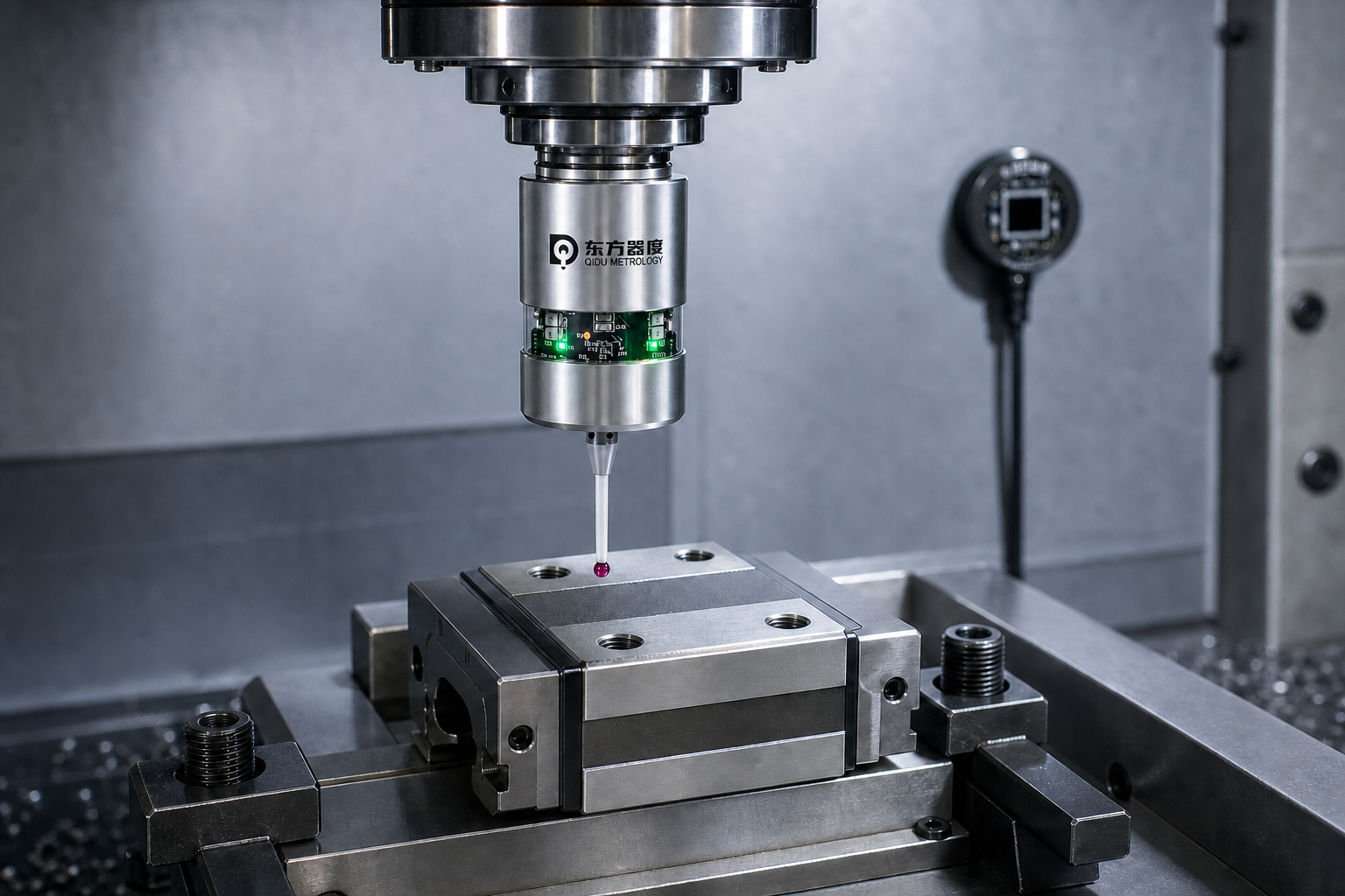
The first compatibility check should identify the CNC control and the machine on which it is installed.
FANUC controllers commonly encountered in machining centers include Series 0i, 16i, 18i, 21i, 30i, 31i, and 32i families. Their functions and available options vary by generation and configuration.
A supplier who knows only that a machine uses “FANUC” cannot reliably determine its installation requirements.
| Compatibility item | What to verify | Why it matters |
|---|---|---|
| FANUC controller | Exact series, model, and software version | Identifies the applicable CNC functions and documentation |
| Machine-tool builder | Manufacturer, machine model, and manufacturing year | Determines machine-specific wiring and PMC logic |
| Installed CNC options | Custom Macro B, skip functions, and relevant probing functions | Establishes whether the intended measurement program can run |
| Existing probing equipment | Spindle probe, tool setter, receiver, and macros | Reveals reusable infrastructure and possible signal conflicts |
| Available machine I/O | Assigned and spare inputs, outputs, and interface connections | Determines integration requirements |
| Probe mounting | Spindle taper, shank specification, available clearance | Determines mechanical installation feasibility |
For retrofit projects, photographs of the controller identification screen and existing probing hardware can save several rounds of technical correspondence.
However, photographs alone cannot establish which software options are enabled. That information should be verified against the machine’s documentation or by a qualified technician.
Not necessarily.
Custom Macro B enables advanced programming operations, including variables, calculations, logical conditions, and custom measurement cycles. It does not automatically guarantee that a usable probe receiver is installed or that the correct skip input is configured.
A machine may support measurement macros but still require interface wiring, additional software configuration, or machine-builder involvement.
The CNC skip function is one of the most important technical considerations when integrating a touch probe.
During a supported G31 probing move, the control monitors an assigned skip signal. When the appropriate trigger signal is received, the CNC records a measurement position and interrupts the remaining commanded movement according to the control configuration.
Measurement macros can then use the captured information to calculate workpiece positions or update offsets.
According to FANUC America’s CNC Options documentation, Custom Macro B provides access to variables, mathematical operations, machine positions, offset data, and logic used in probing applications.
FANUC also describes high-speed skip as a function designed to capture probe-trigger positions using dedicated high-priority circuitry.
These functions serve related purposes but should not be treated as interchangeable.
Standard skip can support measurement operations where its signal response and positional capture characteristics meet the required application.
High-speed skip uses dedicated high-speed processing to improve trigger-position capture. FANUC lists 0.1 ms probe-signal detection for its high-speed skip offering, but this published feature must not be assumed to exist on every controller or machine.
A technician should confirm:
G31 is supported and correctly configured.For common FANUC macro configurations, variables such as #5061, #5062, and #5063 may be used to access captured axis positions. The correct axis mapping and variable behavior must be checked in the applicable control manual.
A critical distinction: a signal changing on a PMC diagnostic screen does not necessarily prove that the probing command is monitoring that signal.
This is where integration becomes more complicated.
A machining center may already use a skip input for a contact tool setter or laser tool measurement system.
Installing a spindle probe introduces another measurement source. The machine must be able to identify and process the appropriate signal for each operation.
Depending on the controller and machine configuration, the solution may involve separate skip channels, supported channel-selection functions, or machine-builder-approved switching logic.
Never assume that two receiver outputs can be electrically connected to the same CNC input without an appropriate interface design.
The existing PMC ladder, skip configuration, and receiver output characteristics should be reviewed before approving a second probing system.
A CNC probe normally communicates with the machine controller through a receiver or interface.
For wireless spindle probes, the receiver detects the probe’s transmitted status and provides electrical signals that the CNC system can process.
That connection must match the machine’s actual I/O architecture.
Receiver power supply
Confirm the required supply voltage, allowable electrical characteristics, and approved connection points. Do not assume that two receivers use identical wiring because they serve the same purpose.
Trigger output
The receiver output must be compatible with the control interface or intermediate circuit. Check whether the system uses a relay, solid-state output, or another supported signaling arrangement.
Signal polarity
The CNC and receiver must agree on the electrical state that represents probe triggering. Incorrect polarity can produce false triggers or prevent the measurement cycle from detecting contact.
Probe activation
Determine how the machine turns the probe on and off.
Some probe systems support M-code-controlled activation. However, the available M-codes and their assigned functions are established by the machine-tool builder.
An M-code used successfully on one FANUC-controlled machine cannot automatically be transferred to another.
Alarm and status signals
Where available, probe-ready, low-battery, and communication-error signals should be handled by the installation software or machine logic.
A trigger signal alone is not a complete diagnostic strategy.
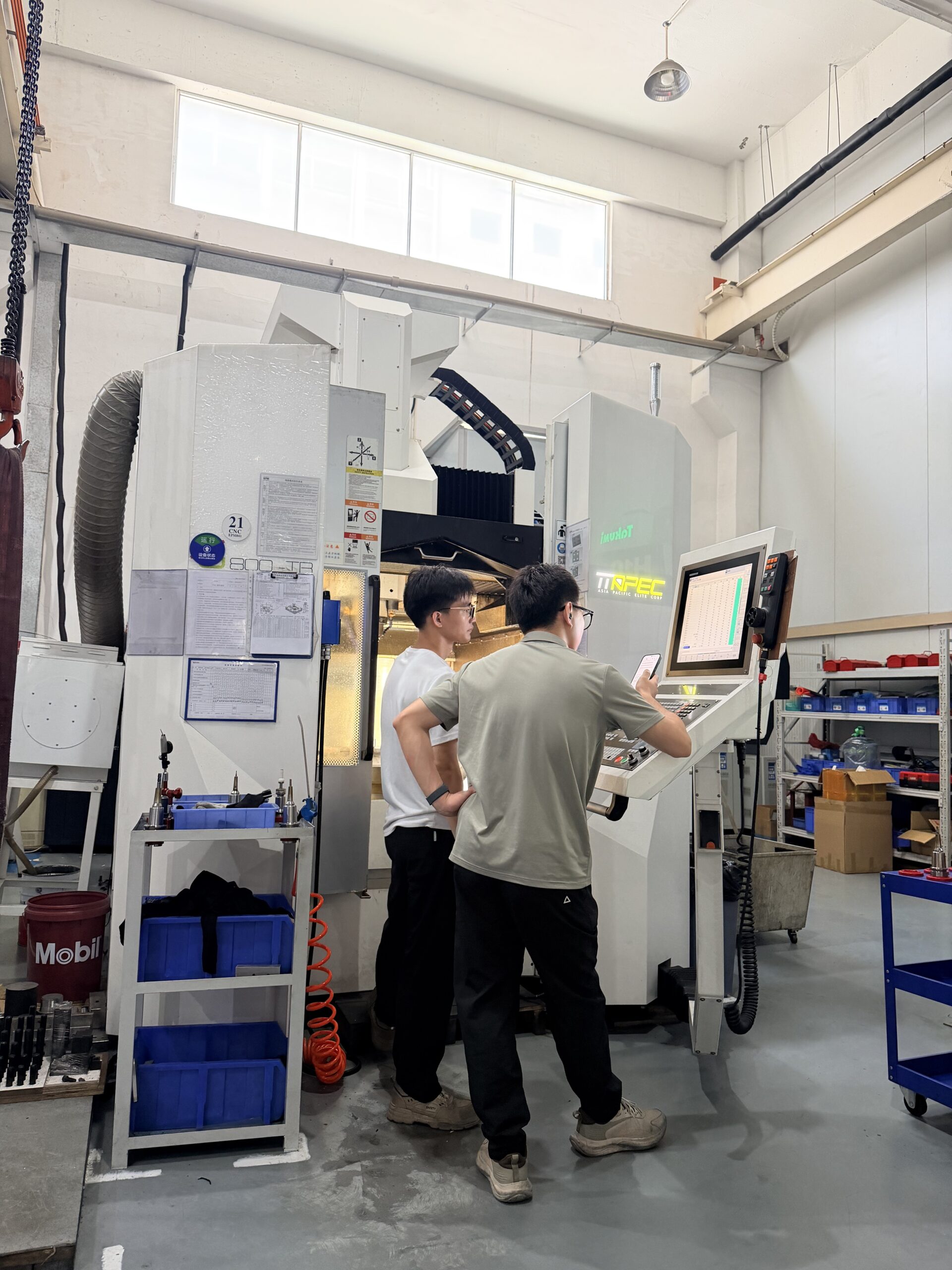
Only when the manufacturer confirms compatibility between the exact probe and receiver models.
Using the same transmission category does not establish compatibility. For example, two radio probes may operate within the same frequency band yet use incompatible communication protocols.
Likewise, infrared optical probes are not automatically interchangeable with every optical receiver.
If a machining center already has probing hardware, provide the receiver model and identification details before ordering a replacement probe.
A complete probe-and-receiver package may be more practical than attempting to reuse an undocumented interface.
Both optical and radio CNC touch probes can be integrated with FANUC-controlled machining centers when the appropriate interface and software requirements are satisfied.
The important difference is how the probe communicates with its receiver, not whether the CNC controller is manufactured by FANUC.
Renishaw’s technical explanation of probe transmission technology distinguishes optical systems, which generally require a clear transmission path, from radio systems, which do not require direct optical line-of-sight.
This difference becomes especially relevant in larger machining centers or machines with complex fixtures.
| Selection factor | Infrared optical probe | Radio transmission probe |
|---|---|---|
| Communication | Infrared light | Radio-frequency transmission |
| Direct optical visibility | Generally required | Not required |
| Compact machining centers | Often suitable | Suitable |
| Large machines | Depends on receiver placement and coverage | Often advantageous |
| Complex fixtures | May obstruct transmission | Less affected by optical obstructions |
| Receiver requirements | Compatible optical interface | Compatible radio interface |
| Installation risks | Blocked optical paths, contamination, receiver orientation | Radio interference, shielding, receiver placement |
| FANUC compatibility | Requires correct interface and macros | Requires correct interface and macros |
Neither option is automatically more accurate because of its transmission method. Measurement performance depends on the complete mechanical and electrical system, probing conditions, and calibration.
Radio transmission is worth evaluating when the machine has a large working envelope, complex workholding, or rotary-axis movements that make optical communication difficult.
For example, the DRP40-P2 radio CNC touch probe uses 2.4 GHz frequency-hopping transmission and a dedicated receiver. Its published operating range is 15 m, subject to actual machine conditions.
This type of system may offer a practical advantage when fixtures obstruct the line of sight between a spindle-mounted probe and an optical receiver.
However, radio transmission does not eliminate the need to verify receiver position, CNC wiring, activation logic, and measurement software.
Optical transmission can be an appropriate solution for compact or medium-sized machining centers where a clear transmission path can be maintained.
The DOP40-PRO infrared CNC touch probe is designed for workpiece setup and on-machine measurement. Its product specifications list a 5 m operating range and a 360° optical transmission envelope, subject to suitable installation conditions.
The receiver must be positioned where the probe can communicate throughout the planned measurement movements.
A 360° transmission envelope should not be interpreted as immunity to physical obstructions.
For buyers evaluating another optical configuration, the DOP40 infrared optical touch probe also supports workpiece positioning and measurement with a separately installed receiver.
Before choosing between these models, compare the complete system configuration, installation drawings, receiver requirements, and controller integration support—not just the stated operating range.
Electrical compatibility is only part of the installation.
The probe must also fit the machine’s spindle, tool-changing system, and available working space.
Check the machine’s spindle interface and the probe’s mounting arrangement.
Common machine-tool interfaces include BT, CAT, and HSK families, but the correct shank must be selected for the exact machine configuration.
A probe body diameter does not identify its mounting interface.
The supplier should confirm:
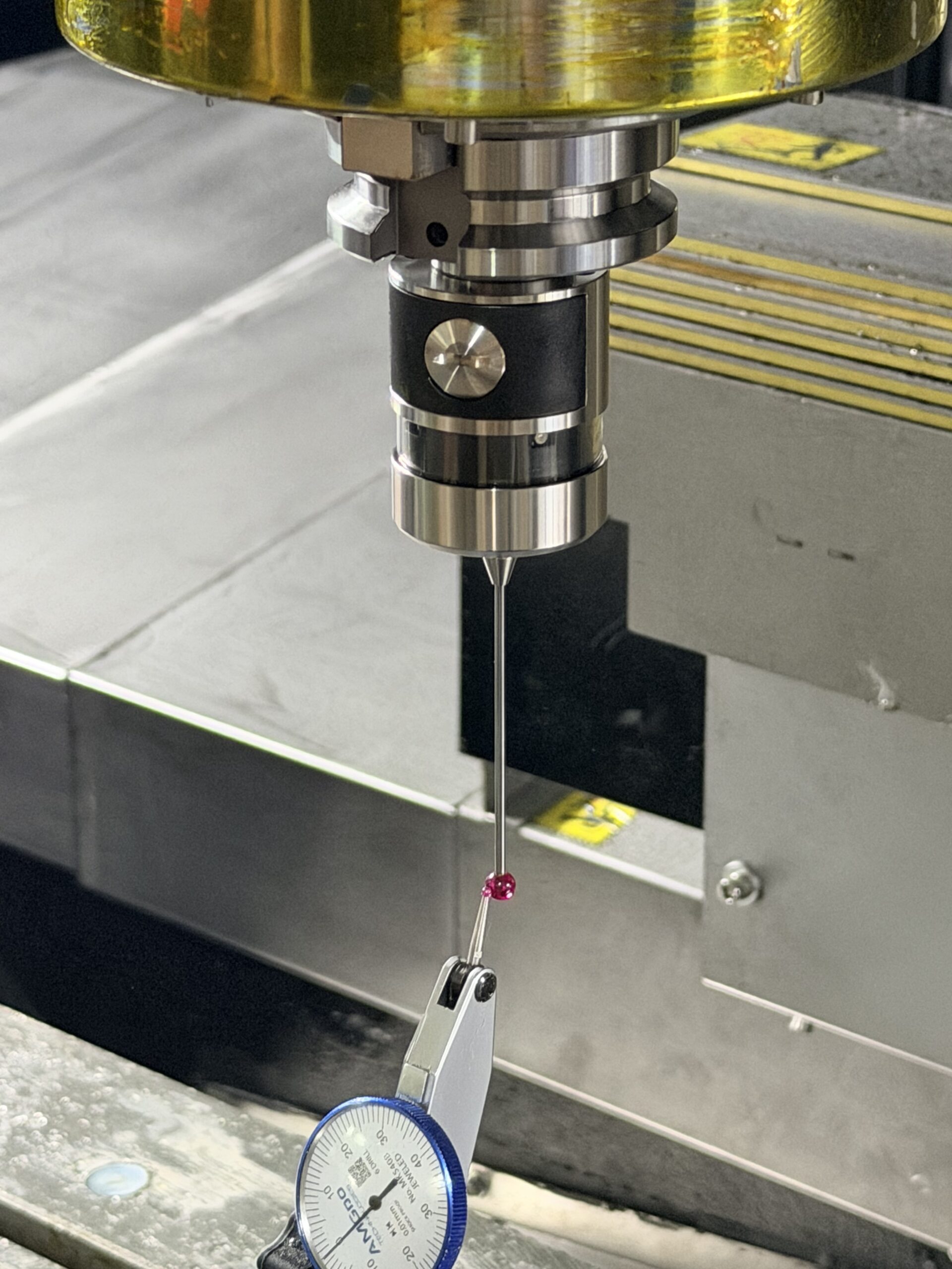
Stylus selection affects measurement reach, contact conditions, and overall measurement behavior.
A longer stylus can help reach recessed features, but it may also increase deflection and sensitivity to vibration.
Select the shortest practical stylus that can reach the required features without unwanted interference.
Probe performance specifications should always be read together with their test conditions.
For example, the DRP40-P2 and DOP40-PRO product information specifies repeatability below 1 μm under defined conditions using a 50 mm stylus and probing speeds of 50–200 mm/min.
Repeatability is not the same as absolute measurement accuracy.
A low repeatability value does not guarantee identical measurement results with a longer stylus, different probing speed, or uncalibrated machine.
For multi-axis machining, verify more than the probe’s physical dimensions.
The intended approach direction, rotary-axis position, tool orientation, fixture clearance, and safe retract path must all be considered.
A probe that physically fits the spindle may still be unsuitable for a particular measurement routine if the programmed approach creates interference.
The measurement program determines what happens after the CNC receives a valid trigger.
A functioning probe does not automatically give the machine the ability to measure bores, establish work offsets, inspect features, or calculate alignment corrections.
Those operations require suitable software.
Depending on the available software, spindle probing may support:
Renishaw’s Inspection Plus macro software illustrates how machine-resident probing software can support basic setup as well as more complex angular and vector measurement cycles.
It also demonstrates why the software package matters independently of the probe hardware.
Not automatically.
Some measurement routines may be adaptable when the new system produces compatible signals and uses the expected control behavior. Other installations depend on specific interface functions, activation commands, calibration procedures, or software conditions.
Before replacing an existing probe, ask whether:
For a new installation, clarify whether the quotation includes the measurement cycles required by the application.
A basic probe package and a complete automated probing solution are not necessarily the same purchase.
A real installation discussion illustrates why compatibility cannot be established from electrical signals alone.
In a December 2025 Practical Machinist discussion about FANUC skip signals, a machinist described configuring a Renishaw laser tool-setting system on a machine with a FANUC 16i controller.
The relevant input was visibly changing on the control, yet the measurement macro continued to report that the system had not triggered.
The discussion identified a mismatch between the skip input being used and the skip command selected by the macro.
Using the appropriate supported G31 P2 configuration addressed that part of the problem. The participant subsequently reported a separate issue with the measurement sequence.
This is a forum-reported installation experience, not a universal FANUC configuration procedure.
Still, it demonstrates two useful lessons.
First, confirming that an electrical input changes is not enough. The active measurement command must monitor the correct signal.
Second, fixing signal recognition does not automatically guarantee that the complete probing cycle operates correctly.
For buyers, this distinction matters because the cost of a probing system includes integration and validation—not just hardware.
A compatibility statement should ideally be supported by a defined commissioning procedure.
Installation testing should be performed by qualified personnel using the machine builder’s electrical documentation and approved safety procedures.
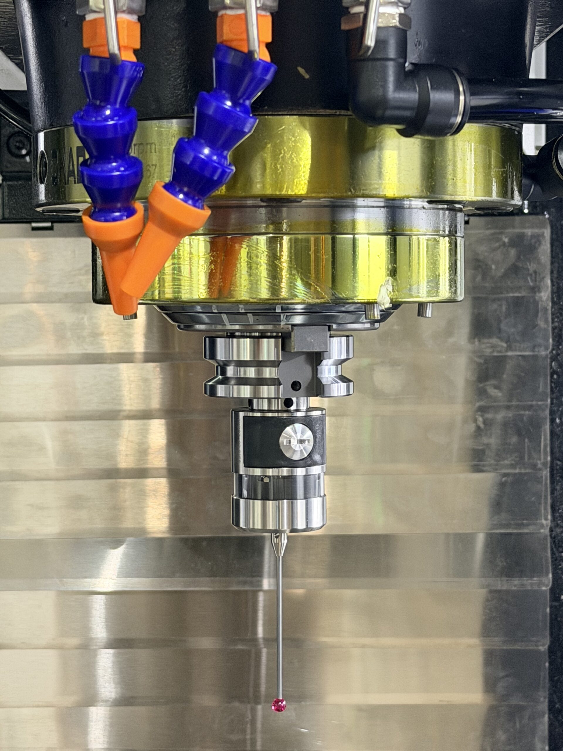
Step 1: Verify the hardware installation
Confirm the mounting shank, stylus, receiver position, electrical connections, and cable protection.
Step 2: Check probe activation and communication
Verify that the probe turns on and off as intended and that the receiver reports the correct status.
Step 3: Confirm signal recognition
With machine motion safely inhibited where appropriate, confirm that the probe trigger changes the expected diagnostic state and is recognized by the configured CNC input.
Step 4: Validate skip behavior
A qualified technician should test the configured skip function using controlled conditions, appropriate clearance, and safe feed rates.
Do not assume that a failed trigger will automatically prevent further commanded movement.
Step 5: Calibrate the complete measurement system
Perform the software manufacturer’s prescribed calibration using appropriate reference features or artifacts.
Calibration must account for the installed stylus and measurement configuration.
Step 6: Verify representative measurement cycles
Test the intended workpiece-setting or inspection routines using known features.
Check the reported values against suitable independent references and the application’s acceptance criteria.
Step 7: Validate failure handling
Confirm the system’s behavior during missing triggers, communication loss, low-battery conditions, and other applicable faults.
The acceptance test should demonstrate that the programmed routine handles abnormal conditions safely.
A successful installation should show that the probe communicates consistently, captures valid measurement information, produces results within defined acceptance limits, and handles relevant error conditions correctly.
A single successful trigger is not sufficient evidence of production readiness.
The lowest probe price does not necessarily produce the lowest installed cost.
For many retrofits, integration work is a major source of uncertainty.
Consider two hypothetical purchases.
Option A: A lower-priced probe is supplied without a confirmed receiver configuration, machine-specific wiring information, or usable measurement macros.
Option B: A somewhat more expensive package includes a compatible receiver, mounting components, documented integration requirements, and appropriate technical support.
Even if Option A has a lower initial purchase price, the additional engineering work could make its overall project cost higher.
The comparison should use the total installed cost rather than the probe price alone.
| Cost component | Questions to ask |
|---|---|
| Probe and stylus | Are the required stylus and accessories included? |
| Mounting shank | Is the correct machine-specific shank supplied? |
| Receiver | Is a compatible receiver included in the quotation? |
| Cabling | Are the required cables and connectors included? |
| Controller options | Are additional FANUC functions or activations needed? |
| Measurement software | Are the required macros supplied and supported? |
| Installation | Who performs wiring and machine configuration? |
| Calibration | Who carries out calibration and acceptance testing? |
| Technical support | Is remote or on-site commissioning assistance available? |
| Spare parts | What are the costs and lead times for replacement components? |
Buyers should also consider downtime associated with commissioning and any future maintenance requirements.
For a machine-tool distributor purchasing multiple probing systems, repeatable installation documentation can be especially valuable. It helps technical teams standardize installation procedures and reduce project-specific engineering work.
A detailed RFQ allows the supplier to assess compatibility before recommending a model.
The most useful information is not simply the machine brand or desired probe diameter. It is the complete relationship between the controller, machine, measurement task, and installation environment.
| Required information | Example or explanation |
|---|---|
| Machine manufacturer | Machine-tool builder name |
| Machine model | Exact model and series |
| Manufacturing year | Year or machine revision |
| CNC controller | FANUC series and full model designation |
| Current probing equipment | Existing probe, receiver, tool setter, and software |
| CNC functions | Confirmed skip and macro capabilities |
| Spindle interface | Exact taper and mounting requirements |
| Measurement application | Workpiece setup, bore measurement, feature inspection, etc. |
| Workpiece characteristics | Relevant dimensions, accessibility, and fixtures |
| Transmission preference | Optical, radio, or supplier recommendation |
| Required probing software | Existing macros or new measurement cycles |
| Installation responsibility | Buyer, machine builder, distributor, or probe supplier |
| Purchasing quantity | Prototype, single installation, or multiple machines |
| Delivery requirements | Destination and required delivery schedule |
Not every buyer will have all the electrical details immediately available.
In that situation, the supplier should identify which information is essential before confirming compatibility and which details can be verified during a technical review.
Before placing an order, request written clarification on the following points:
A supplier who asks detailed compatibility questions before recommending a probe is generally taking a more defensible engineering approach than one who guarantees installation based on the FANUC name alone.
For multi-machine projects, request a compatibility assessment for each machine type before standardizing the procurement specification.
Potentially, yes. Compatibility depends on the exact 0i model, installed software options, skip-signal availability, receiver interface, and machine-builder configuration. Confirm these details before selecting the probe and measurement software.
Custom Macro B is commonly used for automated measurement calculations, offset updates, and probing logic. The specific software requirements depend on the probing application and controller configuration. Verify available functions rather than assuming they are installed.
G31 is a CNC function used to interrupt a supported programmed move when the configured skip signal is received. It can capture measurement-position information for use by probing macros. Exact behavior and configuration depend on the controller.
Yes, when a compatible radio receiver and properly configured CNC interface are available. Radio transmission removes the need for direct optical line-of-sight, but the machine still requires appropriate activation logic, skip-signal handling, and measurement software.
Possibly, but physical similarity does not establish full compatibility. Verify the receiver protocol, shank, electrical signals, activation method, measurement macros, calibration procedure, and any applicable software restrictions before ordering a replacement.
Possible causes include incorrect skip-channel selection, incompatible macro configuration, receiver output issues, calibration problems, or errors in the measurement sequence. Check electrical signal recognition separately from the CNC’s skip-command behavior.
Provide the machine manufacturer and model, exact FANUC controller, existing probing equipment, available CNC functions, spindle interface, and required measurement tasks. Wiring diagrams and controller option information are particularly useful for retrofit projects.